
3D Scanning Frequently Asked Questions
This page contains questions we are frequently asked by our 3d scanning clients. Click the + sign to expand or collapse the sections to view the answers.
WHAT FILES SHOULD I SEND FOR A SCANNING OR DRAWING CONVERSION PROJECT?
Nothing is more important than sending the correct file types to save time and money opening and converting files. This is especially important when dealing with neutral file formats which often have missing geometry. The quality and accuracy of receiving the correct files can save time and money by reducing the editing and re-creating of a part. In theory it is simpler to open a part file and perform modifications to create the intended design, without any conversions.
To help understand the process, we need to define the two major categories of importing CAD files.
NATIVE: CAD files created in the same software package as the one the files will be edited with. For example- if the original files were created with Solidworks, we will use Solidworks to open and modify these files. Theoretically instant and accurate transfers make these files the best option.
Native file limitations- we can open older versions with newer software versions, but can’t open versions that are newer than the one we are using. For example- we can’t open a 2014 file with 2010. If we open a file with the 2015 version, when the file is saved it can only be opened with a 2015 or newer version. If you have a 2014 version, it will not open on your system.
NEUTRAL: CAD files developed to exchange between different software packages.
Neutral file limitations- very few types import perfectly, requiring manual editing of parts. There are numerous versions of many of these file types, and each can have unique problems with certain types of geometry exchanged between different software packages and versions. The files will need “clean up” before they can be imported and modifications can start with existing geometry in the file. Very often, these are the only files available on older parts.
FILE TYPE PREFERENCES FOR SUBMITTING FILES
In order of preference:
- Native Solidworks top level assembly (.sldasm) part (.sldprt) and drawing (.slddrw) files. 2016 to current versions.
- Neutral solid models, a STEP 214 file (.stp).
- Neutral solids, a IGES [ Brep type 186] (.igs)
For surfaces or mixed with solids, a IGES [trimmed surface type 144] (.igs)
Many clients have a .dxf file or a .pdf document. We can open these, but they don’t import as a 3D model, and need to be manually built based on the provided dimensions.
Following are some guidelines for other CAD software files:
Software Company: Best File Format
- AutoCad, Inventor, Navisworks, Revit: DWF-3D
- Microstation: .stp
- NX: .stp, .jt
- ProE/Creo: Native .asm, Neutral .asm, .stp
- Solid Edge: Native .asm, .stp
Many other 3D formats exist, but are not used as often or have specialized applications. All rendering and animation type files are from software packages that use mesh geometry, and will require extensive repairs, patching, and editing to create usable 3D CAD models or drawings. If you don’t have the above types available, send what you have and we can work on the best options. For anyone sending laser scan files or scan data, see the information below for those file types.
WHAT ARE COMMON 3D SCAN DATA FILE TYPES AND USES FOR CAD 3D MODELS
These are pros and cons of the typical export file options for 3D scans after processing the raw scans:
Polygon
Polygon files are a mesh file consisting of multiple triangles and a normal vector that portray the objects shape. This is usually created as the first step in the scanning process. The final polygon file will be optimized and contains no holes. Polygon files are good for free form shapes and complex 3D geometry. They are imported into animation, rendering, and software that handle polygon files. Some CAM software programs can generate a CNC path from these files.
When to consider: Lowest cost, and used for animation & simulation. Many CAM programs can machine direct from these files. Good for free form shape models like sculptures or artwork.
Cons: Not compatible with most CAD software, large file size, and design changes can be difficult. Some geometry and features may not be perfect, no drawing output. Surfacing, rendering, and color need to be applied with other specialized software.
Surface model
Surface models are generated from a polygon model. Surface models contain shape information that can be used in most CAD/CAM systems. This format is very useful for free form shape models with lots of curvature.
When to consider: Intermediate price, and great for free form models. CAM software can use the data to create toolpath for machining. CAD systems can import and work with a surface model, but may have limitations in editing or manipulating the data.
Cons: Surfaces are randomly generated, and often have limited editing capability in many CAD systems. Some geometry may not be perfect, limited dimension capability in drawings.
Feature based solid model
A feature-based solid model recreates the model similar to most solid modeling CAD programs. The difference lies in the fact that the input information is raw scan data, not manually created geometry.
When to consider: Best for mechanical style of parts. Model can be edited in most CAD systems.
Cons: More expensive due to time consuming process to create a finished model. Not recommended for free form models, some editing limitations in many CAD programs.
Parametric feature based solid model
A Parametric feature based solid model includes the most comprehensive information such as design intent, dimensions, and a design history tree.
When to consider: When a fully editable model is needed in a native CAD format, and if future design changes are expected. These files preserve maximum flexibility for file exchange and machining options, as well as future design modifications. Complete documentation for 2D drawings and assembly documents. This is usually the best choice for “reverse engineering” of parts.
Cons: Time consuming to create, and therefore the most expensive design option. Native file format limited to CAD program it was designed on for file exchange with others.
WHAT ARE THE COMMON FILE TYPES AND PREFERRED USES?
- 2D Formats: DXF, DWG
- 3D Neutral Formats: STEP, Parasolid, JT, IGES
- 3D Print Formats: STL, OBJ, AMF/3MF
- Rendering: 3DS, OBJ, FBX
PDF is widely used to send drawings and 3D model documents for clients to view and mark for revisions, but these files are not compatible for direct transfers into CAD systems.
Scan Formats and Uses:
- Point Cloud: Inspection (limited), export to specialized software for further processing.
- Raw Mesh: Inspection (full), export to specialized software for further processing.
Processed Files:
- STL: 3D printing, images for documents, geometry replication with CNC, reference for further design.
- IGES:
- Basic– use if STL files are incompatible with machining software.
- Precise– tooling for production, adding scanned surface to new design.
- STEP: Most common file exchange format between different CAD systems. Used for dimensioning, and shape/volume representation. Often used in an assembly to design around if changes to part is not anticipated.
As you can see, choosing the files you need is not always a simple process. Most projects will require a combination of file types to achieve desired output for each phase of a project.
Choice of appropriate file type for making parts is most dependent on:
- Prototype or production quantities?
- How will the part be manufactured? (Laser cut, molded, 3D printing, etc.)
- What material is the part made from?
- Shop equipment available.
Evaluating these four questions and making these decisions prior to starting a design leads to more accurate parts both for manufacturing and for visual representation, which saves time and money by not revising documents later in the design process.
There might be 12 different ways to design a part for presentation, but only one way to accurately manufacture it economically.
WHY DOES MY .STL FILE NOT SCALE PROPERLY WHEN IMPORTED INTO MY CAD SYSTEM?
The first thing to be aware of is that STL files do not specify what units their distances are in. When a program opens a STL file, it only recognizes that the model measures a certain number of units in each dimension. These units might be meters, inches, kilometers, parsecs, or any other unit that exists.
The majority of 3D printing software uses millimeters for geometry, so it interprets STL files as having units of millimeters. These settings are usually set during initial installation of the software, but can be changed later.
If you are using software (like Blender) that uses arbitrary units, you must scale your model so that 1 unit equals 1 millimeter.
If you are using SolidWorks, or other software that designates its units, it is important to configure the export to use units of millimeters.
Here are two scenarios that are fairly common:
- A model is created with arbitrary units (Blender) and its scale is not considered, and it ends up being only a few units wide. It is exported to an STL file a few units across. The 3D printing software interprets the model as being only a few millimeters across.
- An object is modeled with specific units and its scale is considered. During the export process, the dimensions are converted to some other unit and saved to the STL file. The STL file says that the object is a few hundredths of a unit across. When the 3D printing software opens the file, it interprets units as millimeters and thinks that the object is a few hundredths of a millimeter across.
As you can see from the examples above, unit problems can cause the STL file to import smaller or larger than expected. This is corrected by scaling the model up or down by the conversion factor between millimeters and the exported units.
Our typical default settings for exporting stl files are:
Units: millimeters
Type: binary
Deviation: .01mm
Angle: 5°
CAN I OPEN A CAD FILE TO VIEW MY 3D MODEL WITHOUT A CAD PROGRAM?
Many 3D CAD files will only open on the specific software package it was designed on. We almost always include a neutral file format that can be opened by many different programs. Most of the major CAD packages offer free viewers that you can download, allowing you to view the file, but not offering any editing or printing functions.
The links below are for the two most commonly used viewers:
Link for Adobe Acrobat DC free viewer-
https://helpx.adobe.com/acrobat/using/displaying-3d-models-pdfs.html
Solidworks viewer- To download eDrawings, go to www.edrawings.com.
Instructions for using them are contained in help files included with the downloads.
HOW DO I SEND 3D FILES THAT ARE VERY LARGE?
Files up to 20Mb can generally be attached to an e-mail. Larger files can be sent via Dropbox with a link we provide.
WHY IS THERE A WIDE VARIATION IN PRICING OF 3D SCANNING OF PARTS?
Selecting the best 3D scanner is based on the size of part, complexity of geometry, accuracy requirements, and which file output types you will require. The chart below shows the basic 3d scan cost (not including editing or final file preparation) to help explain where some of the cost differences occur on 3d scanning jobs.
These prices are for mesh files (.stl or .obj files), and are only the starting point to creating models/drawings that most jobs will need. If you only require .stl files and will not need to edit the file in the future, these scan prices will only require minor edits to prepare a finished .stl file.
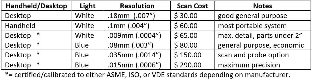
For clients requiring surface or 3D solid models, additional editing and conversion of the scan files are required. This incurs additional charges based on the complexity and accuracy requirements of the part. The additional time can add 2-6 times the scan cost, depending on the file type required.
As an example: for simple geometry if the first scanner is used for your part, and a non-parametric 3D model (.stp) file is needed, the total cost would be approximately $65-75.
A complex part using scanner #3 requiring a parametric native Solidworks part file would be approximately $225-285.
The same part requiring only the .stl file would be $82. Hopefully this chart will help clarify the cost differences between projects based on the scanner used and file output requirements.
Explore the possibilities